>home >support >Fan Blades
Fan Blade Identification and Removal/Installation

Only certified technicians should attempt servicing the air conditioning unit.
Disconnect the power to the unit before any service is attempted !!!
Remember Safety First !!
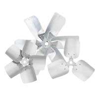
Fan Blade Identification
Fan Blade Diameter + Number of Blades + Pitch + RPM
= This will let us select the Motor HP Required
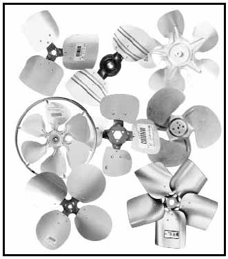
NUMBER OF BLADES
It is common for propellers of slightly
different pitches and number of blades to
achieve the same performance. This is
possible because of the various blade shapes
and forms employed by each manufacturer.
It is, however, usually desirable for a
replacement propeller to have the same
number of blades as the original propeller.
PROPELLER PITCHES
The pitches of cross-referenced propellers
are often not identical for the same reasons
stated above. It is common for propellers
of slightly different pitches to achieve the
same performance.
Pitch is measured at the spider lobe, not
on the blade.
ROTATION
The propeller’s rotation direction is
determined to be clockwise (CW) or
counterclockwise (CCW) when viewed
from the air discharge side (air blowing in
your face). The discharge side is the
concave (“cupped”) side of the blade.
Imagine standing in a sandbox and
dropping the propeller face up, or face
down, on the sand. Regardless of which
side is up, the direction of rotation is the
same as the direction required to turn the
propeller into the sand.
INSTALLATION TIPS
1. Disconnect electrical power before
working on unit.
2. Note location of old propeller in unit.
Remove old propeller from motor shaft.
Use a proper type of puller. Do not
hammer on propeller as this can result
in a bent shaft or bearing damage.
3. Remove burrs and rust from motor
shaft.
4. Use extra care in handling and
installation. Locate interchangeable
hub on desired side of propeller (air
intake or air discharge). Attach hub
to propeller with three (3) screws
provided (to determine side to locate
hub on, it will be helpful to note hub
location of old propeller). Tighten
screws to approximately 30 in.-lbs..
5. Place propeller on motor shaft in unit
and locate in approximately the same
position as the old propeller.
6. Make sure that the propeller will be
rotating in the right direction.
7. Fasten the propeller to the motor shaft
by tightening set screws securely. Be
sure to align set screw with flat on
motor shaft.
Set Screw Recommended
Diameter Seating Torque
1/4" = 70 in. - lbs.
5/6" = 130 in. - lbs.
8. Rotate the propeller by hand to make
sure that the blades clear any obstructions
by at least 1/4″.
NOTE: All above data is for reference purposes only